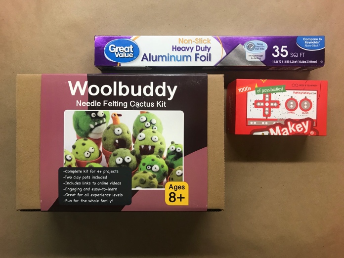
O | Gathering the “stuff”
Inspiration (aka online tutorials as starting point)
https://www.youtube.com/watch?v=sAPGw0SD1DE
https://www.instructables.com/id/IKEA-Infinity-Mirror/
https://www.instructables.com/id/Arduino-Infinity-Mirror-Bluetooth-Sound-Reactive/
https://www.hackster.io/Ben_Finio/arduino-controlled-rgb-led-infinity-mirror-4935f1
http://www.johnlangdon.net/thoughts/types-of-ambigrams/
https://www.hackster.io/Lucas_Ainsworth/kaleidoscope-infinity-mirror-bdcd36
Infinity Mirror
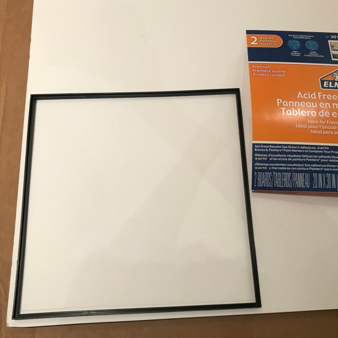
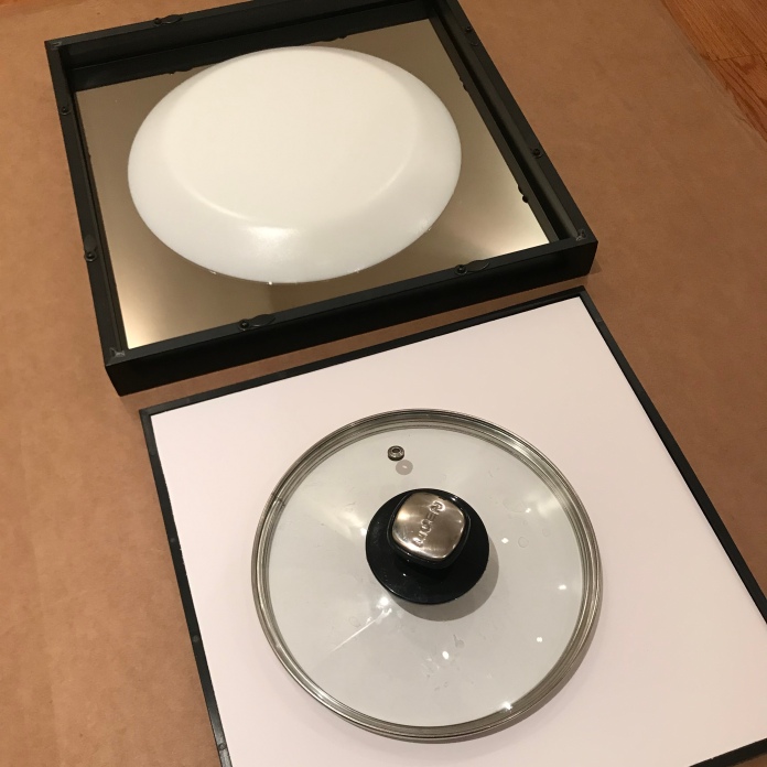
Black Adjustable-Depth Shadow Box By Studio Décor®
12 x 12 Acrylic See-through Mirror
Essentially, one just needs a mirror and a see-through mirror, or two-way mirror with a frame/ stand to place them over each other with min 1cm gap (or however think is the LED lights).
Electronics to build a LED clock
Adafruit Trinket – Mini Microcontroller – 5V – in the end, I used Arduino Uno instead
NeoPixel 1/4 60 Ring – 4 to form a complete circle
Adafruit PCF8523 Real Time Clock Assembled Breakout Board
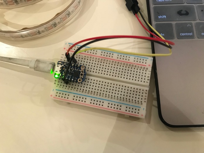
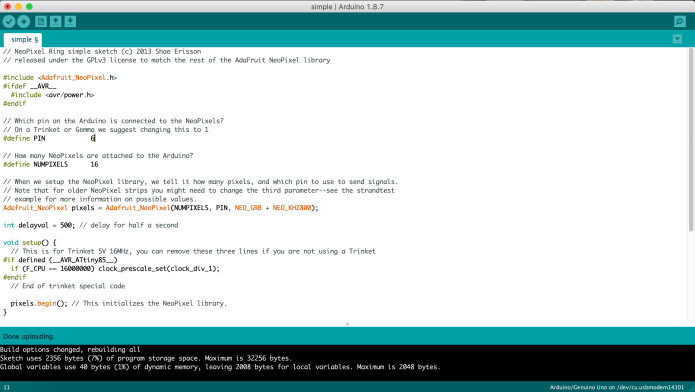
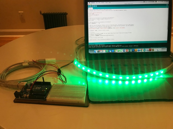
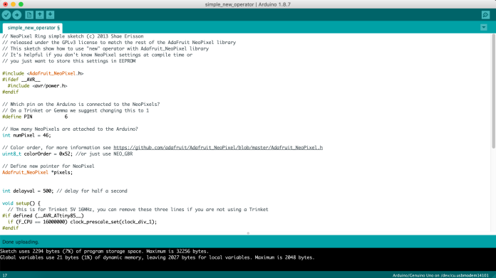
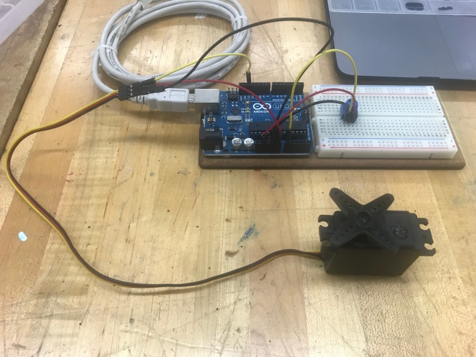
1 | Testing!
Unable to upload program to Trinket…
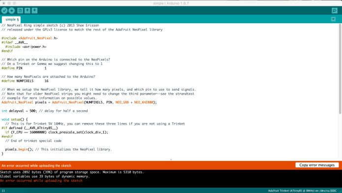
… seems like the Trinket does not work well with USB 3.0 port.

So I reverted back to the trusty Arduino UNO.
2 | Add RTC to Circuit
using this tutorial: https://learn.adafruit.com/neopixel-60-ring-clock
Adafruit DS1307 Real Time Clock Assembled Breakout Board
https://www.adafruit.com/product/3296
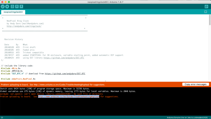
But it worked once, then did not work… Apparently it is not as reliable to use power from USB as compared to direct power. So…
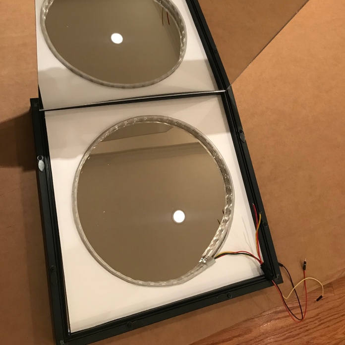
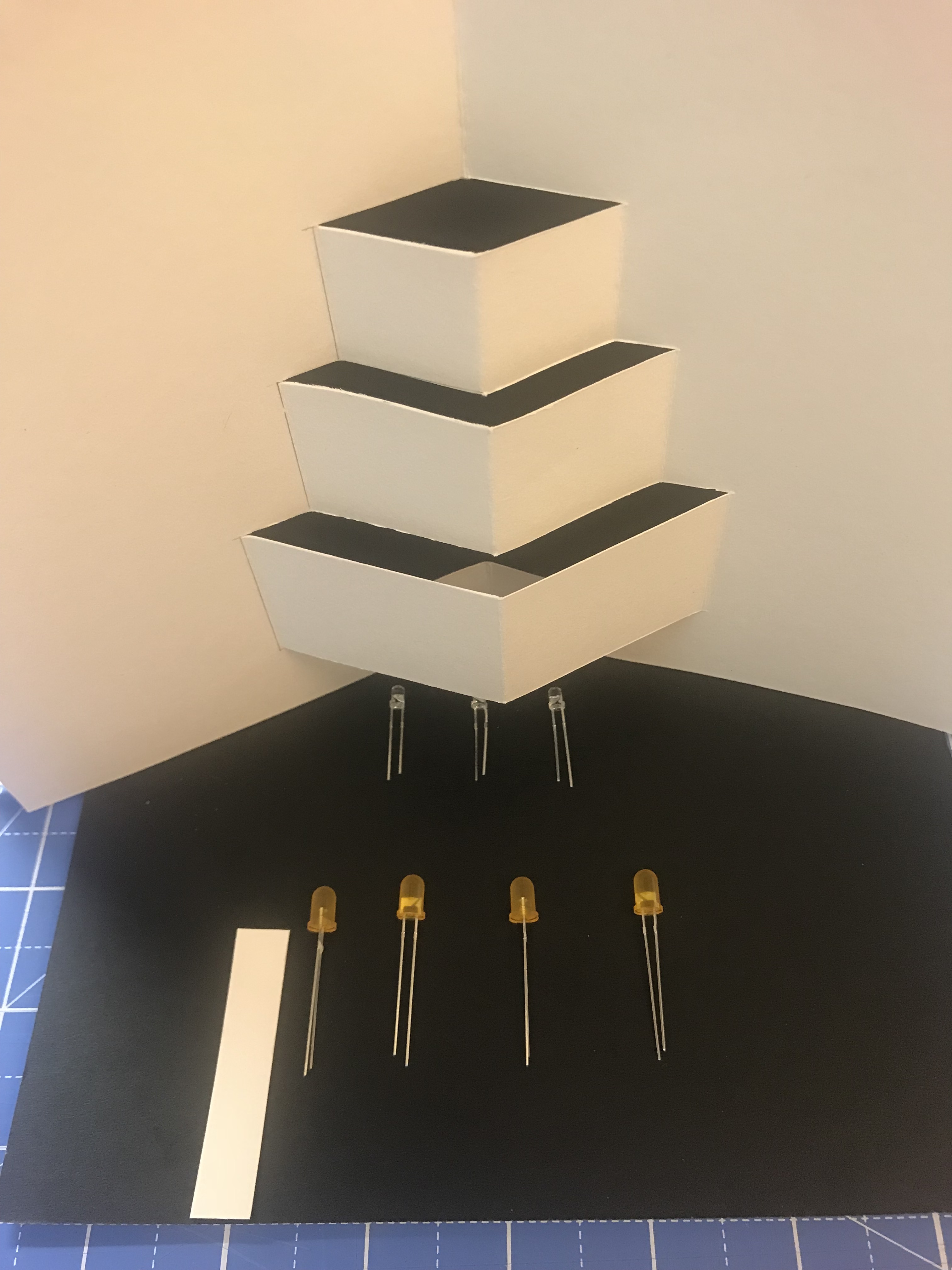
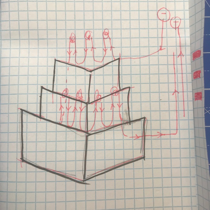
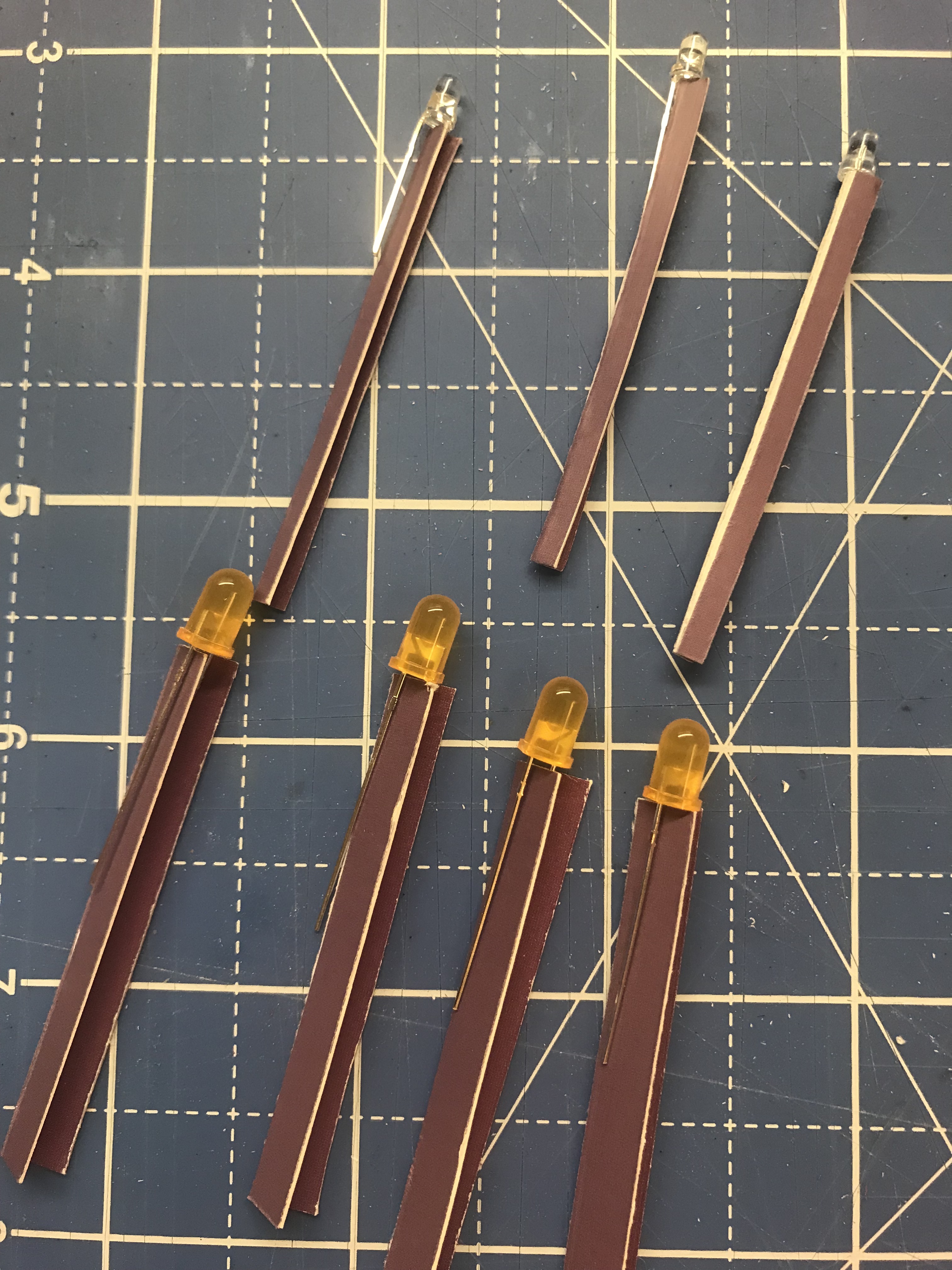
2 | Building the Infinity Mirror

3 | Tweaking?
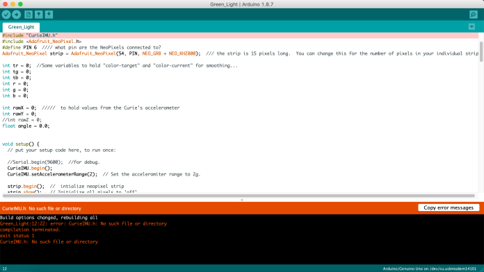
SIGH…
Couldn’t find that library.
Summary & Reflection
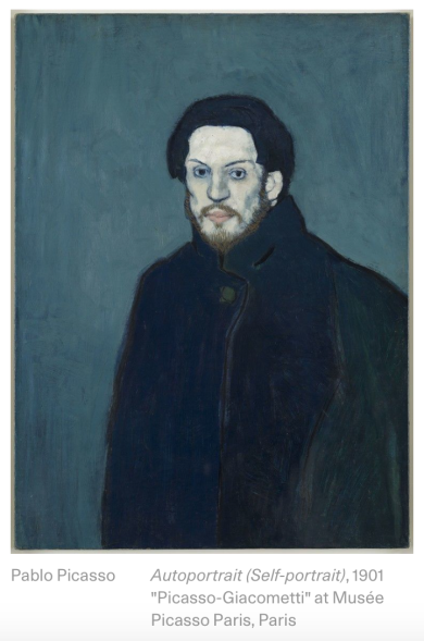
- I wanted to create – an infinity clock inspired by my favourite jewerly designer who said that “Then watches were only chronometers – measurers of time, which one got constantly caught out by. I wanted to free people form the slavery of time, I wanted to make a watch which reminded one that life is here and now, so I created a watch with a mirror face, no numbers and a simple second hand. A watch should not make us prisoners of time–but liberate us. Perhaps it is possible to make a timepiece which more intensely perceives the Here and Now. The watch is open ended to symbolize that time should not bind us, and the dial like a mirror reminds us that life is now.”
- But I didn’t manage to make what I wanted to because of certain technical challenges which could be due to my lack of experiences (which resulted in alot of digging around and troubleshooting)
-
- Trinket did not work with USB 3.0. -> Although, if I had read everything about it before deciding to use it, then I won’t have this problem.
- Real Time Clock
- Firstly, I must say that I underestimated the difficulty of buying a CR1220 battery. Should have ordered it together with the order from Adafruit (would have saved $ too!).
- Secondly, my RTC only worked for one time and it stopped. I suspect 1) the USB input couldn’t supply enough battery, should have gotten an external adaptor. 2) I am also not sure if I have “burnt” the circuit board while soldering. I remembered having a tiny explosion of fumes when I was soldering.
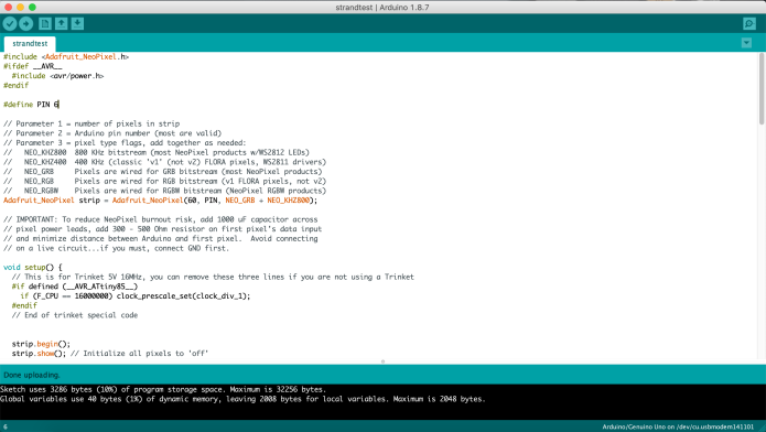
- Problem with coding, loading “libraries”, selecting the right board, port etc. Enough said. Because I don’t exactly know how to start discribing the agony I had while trying to troubleshoot and google “how to download code and uncompress in arduino sketch folder” (see below).
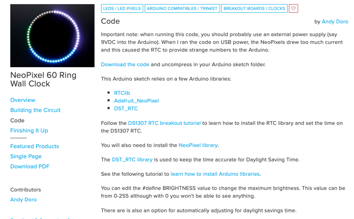
- Actually, as I am writing this, I remember as I tried to follow this tutorial, I had moments where I felt like I should have read the entire tutorial and understand it completely before I try following it. Because, the “important note” (screenshot above), was only apparent to me after I had the RTC issue. Hence, it got me thinking about the Art of Creating Online Resources – what might be the best way to “document” or create tutrials?
- I wished I had more time to play with arduino… because I feel like I am just starting to get the hang of it (at least circuiting), and I want to learn more about how to code. They still look like a very foreign language to me.

HANG ON…
https://www.tweaking4all.com/hardware/arduino/adruino-led-strip-effects/#LEDStripEffectMeteorRain
finally figured out!
#include “FastLED.h”
#define NUM_LEDS 60
CRGB leds[NUM_LEDS];
#define PIN 6
void setup()
{
FastLED.addLeds(leds, NUM_LEDS).setCorrection( TypicalLEDStrip );
}
void loop() {
meteorRain(0xff,0xff,0xff,10, 64, true, 30);
}
void meteorRain(byte red, byte green, byte blue, byte meteorSize, byte meteorTrailDecay, boolean meteorRandomDecay, int SpeedDelay) {
setAll(0,0,0);
for(int i = 0; i < NUM_LEDS+NUM_LEDS; i++) {
// fade brightness all LEDs one step
for(int j=0; j5) ) {
fadeToBlack(j, meteorTrailDecay );
}
}
// draw meteor
for(int j = 0; j < meteorSize; j++) {
if( ( i-j =0) ) {
setPixel(i-j, red, green, blue);
}
}
showStrip();
delay(SpeedDelay);
}
}
void fadeToBlack(int ledNo, byte fadeValue) {
#ifdef ADAFRUIT_NEOPIXEL_H
// NeoPixel
uint32_t oldColor;
uint8_t r, g, b;
int value;
oldColor = strip.getPixelColor(ledNo);
r = (oldColor & 0x00ff0000UL) >> 16;
g = (oldColor & 0x0000ff00UL) >> 8;
b = (oldColor & 0x000000ffUL);
r=(r<=10)? 0 : (int) r-(r*fadeValue/256);
g=(g<=10)? 0 : (int) g-(g*fadeValue/256);
b=(b<=10)? 0 : (int) b-(b*fadeValue/256);
strip.setPixelColor(ledNo, r,g,b);
#endif
#ifndef ADAFRUIT_NEOPIXEL_H
// FastLED
leds[ledNo].fadeToBlackBy( fadeValue );
#endif
}
void showStrip() {
#ifdef ADAFRUIT_NEOPIXEL_H
// NeoPixel
strip.show();
#endif
#ifndef ADAFRUIT_NEOPIXEL_H
// FastLED
FastLED.show();
#endif
}
void setPixel(int Pixel, byte red, byte green, byte blue) {
#ifdef ADAFRUIT_NEOPIXEL_H
// NeoPixel
strip.setPixelColor(Pixel, strip.Color(red, green, blue));
#endif
#ifndef ADAFRUIT_NEOPIXEL_H
// FastLED
leds[Pixel].r = red;
leds[Pixel].g = green;
leds[Pixel].b = blue;
#endif
}
void setAll(byte red, byte green, byte blue) {
for(int i = 0; i < NUM_LEDS; i++ ) {
setPixel(i, red, green, blue);
}
showStrip();
}


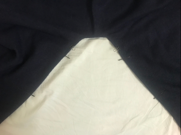
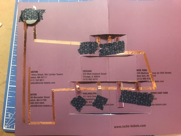
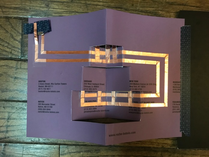


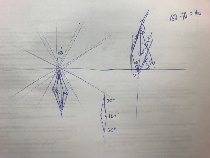
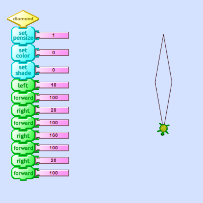
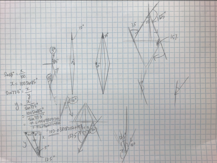
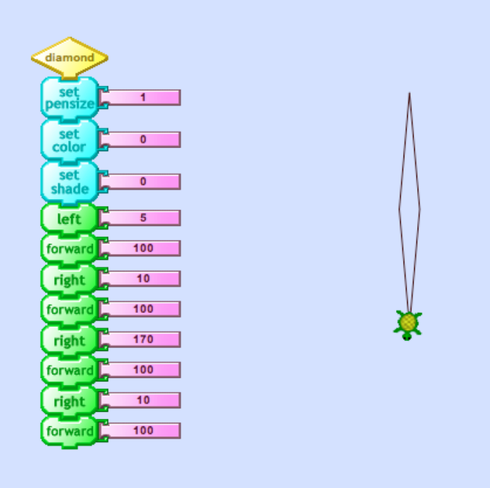
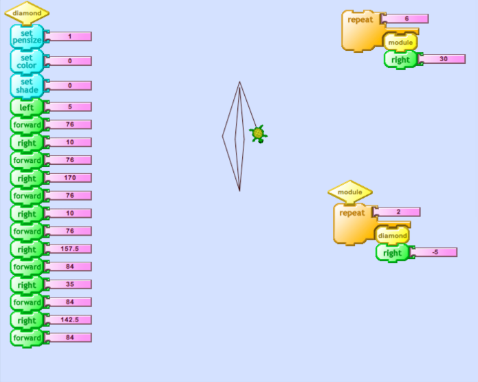
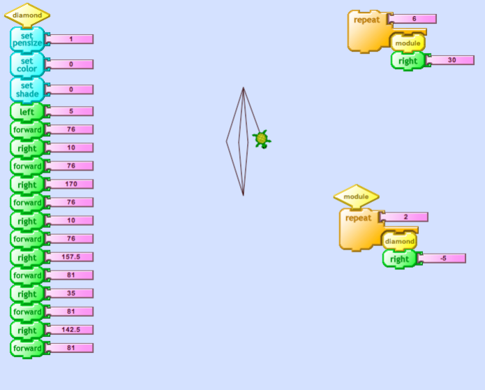
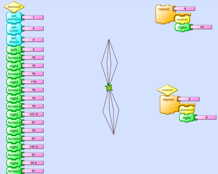
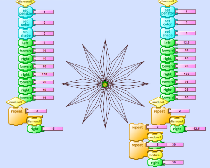
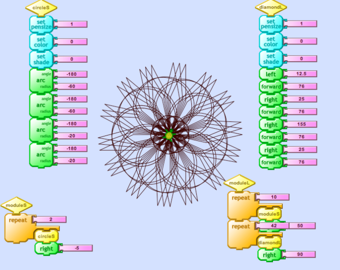
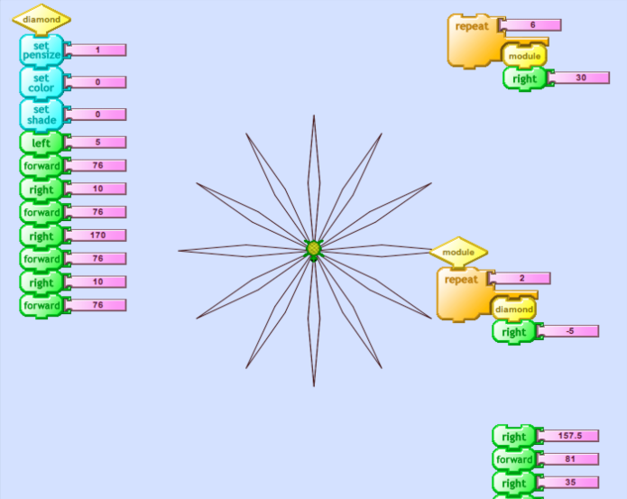 it was difficult to create the outer quadrilateral accurately. I attempted to use my rusty trigonometry calculation to figure out the relationship between the angles and length of the sides, but this happened – the tips of the quadrilaterals were not aligned.